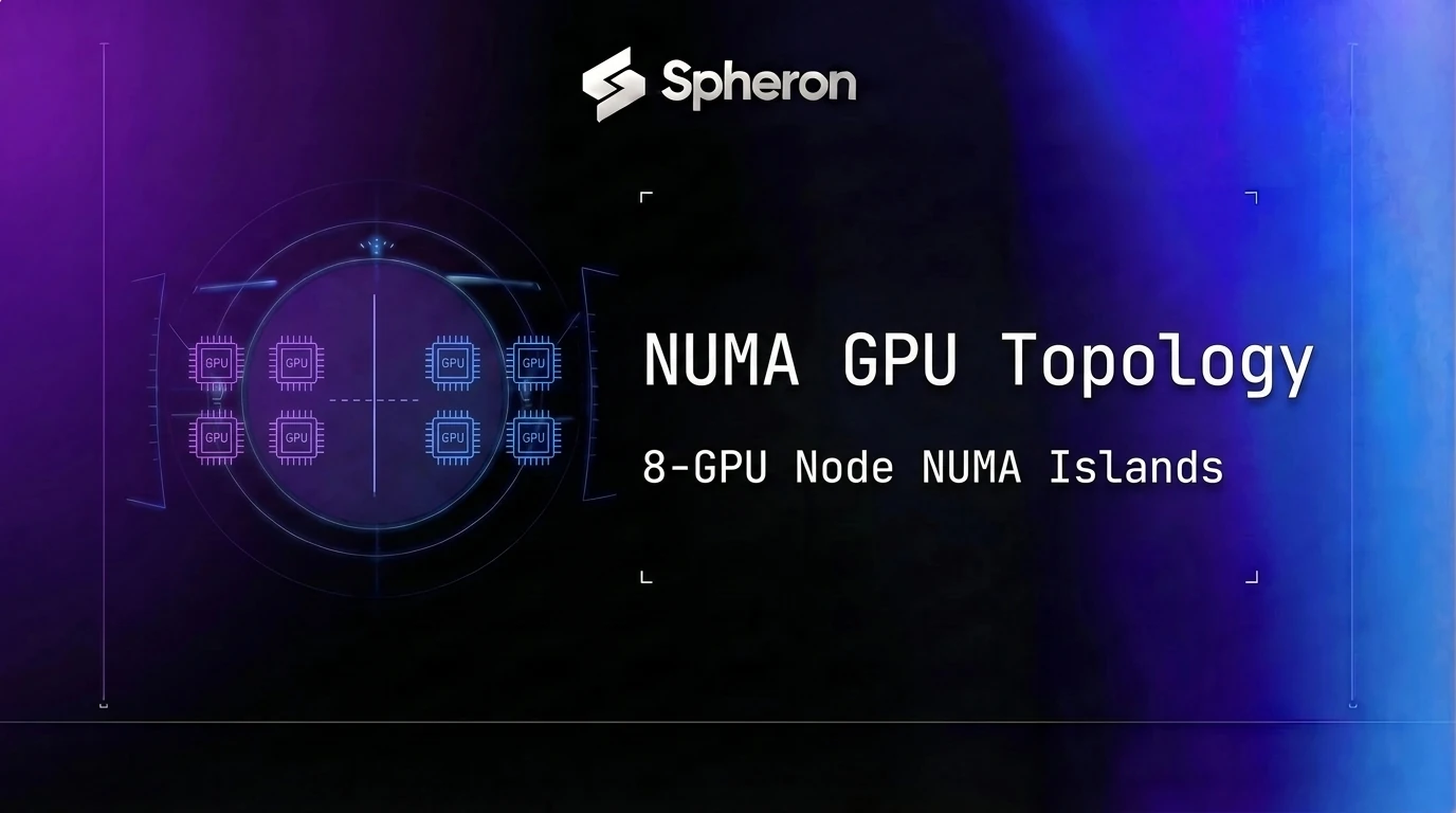
A tensor-parallel job on our 8-GPU node scaled cleanly from 1 GPU to 4, then hit a wall the moment we pushed it to use all 8: per-GPU throughput held flat through the first four cards, then dropped hard as soon as the parallel group crossed into the second four. Nothing about the hardware looked wrong. Drivers matched, GPUs reported healthy, batch size untouched. The actual problem was NUMA GPU topology: a dual-socket, PCIe-only 8-GPU server isn't one pool of 8 GPUs by default. It's two 4-GPU islands, bridged only by the socket-to-socket interconnect and host memory, and the failure only shows up once a tensor-parallel group tries to straddle both.
TL;DR: NUMA GPU Topology and the 8-GPU Scaling Cliff
- The pattern: on PCIe-only 8-GPU servers, GPUs commonly split into two separate 4-GPU domains, one per CPU socket, rather than one flat 8-GPU pool.
- Why it bites tensor parallelism: cross-socket traffic crosses UPI, which is shared with memory coherency and I/O, not reserved for GPU traffic.
- How to catch it: run
nvidia-smi topo -mand read the connection codes between GPU pairs, then confirm withlspciand NUMA affinity checks rather than trusting SYS alone. - The fix: size tensor-parallel groups to the island (4 GPUs), not the node (8 GPUs). Spheron's bare-metal H100 instances give direct shell access to run this diagnostic before committing a training run.
On the job that flagged this for us, a tensor-parallel Llama 3.1 70B serving workload, per-GPU throughput sat at roughly 3,150 tokens/sec across the first four GPUs, in line with what we'd measured on a single 4-GPU run. Extending the same tensor-parallel group to all 8 GPUs dropped per-GPU throughput to around 1,780 tokens/sec, a 43% fall instead of the near-flat scaling curve every prior step had shown. GPU utilization stayed above 90% the whole time, which is what made it confusing: the compute wasn't idle, the all-reduce after every layer was just taking far longer to complete once it had to leave the socket.
The Symptom: Tensor-Parallel Throughput That Didn't Scale Past 4 GPUs
The job was ordinary: tensor-parallel inference and fine-tuning work on an 8-GPU PCIe node, the kind of box a lot of teams rent expecting it to behave like a smaller HGX system. Scaling from 1 to 2 to 4 GPUs looked exactly the way a topology diagram promises: near-linear throughput gains as each additional card joined the tensor-parallel group. Then we asked for 8.
This isn't a one-off. It's a documented, repeatable failure mode on PCIe-based multi-GPU servers, and one of the clearest public writeups of just how invisible it can be comes from a pair of nominally identical 8x H100 servers that produced 3,000 tokens/sec on one and 900 tokens/sec on the other for the same workload. Two boxes, same spec sheet, more than 3x apart in real throughput. That's the shape of the problem: nothing on the invoice or the GPU listing tells you which box you got.
The general-purpose version of the same effect shows up in raw compute benchmarks too. In an HPL-AI memory-bound benchmark, a 4-GPU A100 SXM4 system reached roughly 485 TFLOPS, while a comparable 4-GPU A100 PCIe system reached roughly 110 TFLOPS. Our node wasn't comparing SXM against PCIe; it was PCIe against itself, but the mechanism, an all-reduce forced onto a slower path than the workload assumed, is identical.
Frank Denneman, describing multi-GPU topology inside a single host, puts the inflection point at exactly this configuration size: "This is also the first configuration where adding more GPUs does not automatically improve performance. Going from two to four GPUs in a single VM introduces a topology boundary that can reduce scaling efficiency." Our data agreed almost exactly with where he places the cliff, just one GPU group further out: the boundary we hit sat between 4 and 8, not between 2 and 4, because our particular node kept a healthy 4-GPU domain on each socket before the second domain had to be crossed.
Diagnosing NUMA GPU Topology With nvidia-smi topo -m
The first diagnostic on any multi-GPU node, healthy or not, is the same command:
nvidia-smi topo -mOn a PCIe-only, dual-socket 8-GPU server, the output pattern typically looks like this:
        GPU0  GPU1  GPU2  GPU3  GPU4  GPU5  GPU6  GPU7  CPU Affinity
GPU0     X    PIX   PXB   PXB   SYS   SYS   SYS   SYS   0-31
GPU1    PIX    X    PXB   PXB   SYS   SYS   SYS   SYS   0-31
GPU2    PXB   PXB    X    PIX   SYS   SYS   SYS   SYS   0-31
GPU3    PXB   PXB   PIX    X    SYS   SYS   SYS   SYS   0-31
GPU4    SYS   SYS   SYS   SYS    X    PIX   PXB   PXB   32-63
GPU5    SYS   SYS   SYS   SYS   PIX    X    PXB   PXB   32-63
GPU6    SYS   SYS   SYS   SYS   PXB   PXB    X    PIX   32-63
GPU7    SYS   SYS   SYS   SYS   PXB   PXB   PIX    X    32-63
Read that matrix left to right and the split is immediate. GPU0 through GPU3 connect to each other via PIX or PXB, meaning they sit under a shared PCIe switch fabric on one CPU's root complex. GPU4 through GPU7 do the same among themselves. But every entry between a GPU in the first group and a GPU in the second group reads SYS. That's the island boundary, and the CPU Affinity column, showing cores 0-31 for the first four GPUs and 32-63 for the second four, confirms it lines up with the two physical sockets.
This is a genuinely different picture from an NVSwitch-equipped HGX node, where every GPU-to-GPU pair shows an NVLink code (NV18 on an H100 or H200 HGX system) regardless of which socket manages it. On a PCIe-only box, there is no fabric tying the two halves together at the GPU level at all. If you're deciding between SXM and PCIe form factors before you even rent, the tradeoff underneath this exact split, and where PCIe's NVLink bridging tops out at just 2 GPUs before falling back to plain PCIe Gen4 x16, is covered in our A100 deployment guide comparing SXM and PCIe.
Reading the Matrix: What NV18, NODE, PHB, and SYS Actually Mean
The connection codes nvidia-smi topo -m prints aren't arbitrary shorthand; each one maps to a specific point in PCI switch, CPU, and GPU Direct server topology:
| Code | What it means |
|---|---|
NVx | A bonded NVLink connection, where x is the link count (an HGX H100/H200 pair typically shows NV18 via NVSwitch) |
PIX | The two devices share a single PCIe switch |
PXB | The two devices share multiple PCIe bridges but not the host bridge |
PHB | The connection passes through a PCIe host bridge |
NODE | Same NUMA node, but a different PCIe host bridge |
SYS | Crosses PCIe plus the SMP/NUMA interconnect (QPI or UPI) |
Codes get slower as you move down that list. NVx is the fastest path available and only appears when dedicated NVLink hardware connects the pair. PIX and PXB stay entirely within one PCIe switch fabric, which is fast but still bottlenecked to whatever that fabric's aggregate bandwidth is. PHB and NODE mean the traffic has to go up to a host bridge, adding latency but usually staying inside one NUMA node. SYS is the one to watch for on a multi-socket box: it means the request has to leave the local socket entirely.
None of these codes describe raw bandwidth numbers on their own, they describe topology distance. On an A100 PCIe system, the practical bandwidth consequence of that distance is concrete: a bonded NVLink pair (where present) runs at 600 GB/s, but once communication has to fall back to the server's PCIe Gen4 x16 links, which top out around 64 GB/s, that's roughly a 10x drop. A PIX-to-SYS jump in the matrix is the topology signature of exactly that kind of bandwidth cliff.
The SYS Trap: Why the Legend Doesn't Always Match the Real NUMA Node
Here's the part that made this harder to diagnose than reading the matrix once and moving on. SYS tells you a connection crosses the SMP/NUMA interconnect. It does not, by itself, reliably tell you which physical NUMA node either GPU in that pair is actually bound to, and on a node with an unusual PCIe switch topology or BIOS-level interleaving setting, the CPU Affinity column nvidia-smi topo -m prints can lag or misrepresent the OS's own view of GPU-to-NUMA-node assignment.
Treat the matrix as the first signal, not the last one. Two commands close the gap:
# Physical PCIe tree, showing which root complex each GPU actually hangs off
lspci -tv

# Kernel's own view of which NUMA node owns each PCIe device
cat /sys/bus/pci/devices/<gpu-pci-address>/numa_node

# System-wide NUMA layout, to sanity-check the two numbers above against each other
numactl --hardware
If lspci -tv shows a GPU under a root complex the matrix's CPU Affinity column didn't predict, trust lspci and the kernel's numa_node file, since those come from the platform's own ACPI/SRAT tables rather than from NCCL's or nvidia-smi's topology inference.
There's a second, related trap worth checking at the same time: PCIe Access Control Services (ACS), when enabled in BIOS, forces peer-to-peer GPU traffic through the CPU root complex instead of allowing direct GPU-to-GPU DMA between devices sitting on the same PCIe switch. You can check it directly:
lspci -vvv | grep -i acsctlAn nvidia-smi topo -m matrix showing PIX between two GPUs still looks fast on paper if ACS is silently routing that "same switch" traffic through the CPU anyway.
Why Two 4-GPU Islands Happen: Dual-Socket PCIe and the UPI Bottleneck
The island split isn't a manufacturing defect or a misconfigured server, it's the direct, predictable result of how dual-socket x86 servers are built. Each CPU socket owns its own PCIe root complex and its own bank of directly-attached memory. On an 8-GPU chassis without a dedicated GPU-to-GPU switch fabric like NVSwitch, the only sane way to wire 8 PCIe GPUs into two sockets is 4 GPUs per socket, each group hanging off its own root complex.
The two halves aren't unconnected. They talk to each other through the CPU-to-CPU interconnect, Intel UPI or AMD's Infinity Fabric depending on the platform, which is also the same path that carries memory coherency traffic, remote memory access requests, and I/O originating from devices attached to the other socket. It is not a lane reserved for GPU traffic; it's general-purpose plumbing that GPU communication has to share with everything else the two CPUs need to coordinate. That's a fundamentally different resource than a dedicated NVLink fabric, and it behaves like one under load: fine at low utilization, congested the moment a tensor-parallel all-reduce tries to push a full gradient tensor across it on every layer.
The latency cost of that shared path is measurable even outside GPU workloads. On AMD EPYC hardware, cross-socket memory access can incur roughly 3x the latency of same-socket local access. None of those numbers are GPU-specific; they're a description of what the UPI link is actually built for, and why asking it to also carry tensor-parallel gradient traffic at full tilt is asking it to do a job it wasn't sized for.
For the aggregate bandwidth context that makes this concrete: NVLink 4 on an H100 or H200 HGX system delivers up to 900 GB/s per GPU, and NVLink 5 on B200 reaches 1,800 GB/s. UPI and Infinity Fabric links aren't in that class, and they were never meant to be; they exist to keep two CPUs cache-coherent, not to move gradient tensors. Our guide to multi-node training without InfiniBand covers the same bandwidth gap at the network level, between nodes rather than between sockets in one node, and the arithmetic is the same in both places: a link built for something other than tensor-parallel all-reduce will bottleneck the moment you route that traffic across it anyway.
The Fix: Sizing Tensor-Parallel Groups to the Island, Not the Node
Once the matrix confirms two 4-GPU islands, the fix is a configuration change, not a hardware change: stop treating the node as one 8-way tensor-parallel domain and start treating it as two 4-way domains connected the way you'd connect two separate nodes.
Concretely, that means:
- Set your tensor-parallel group size to 4, matching the island, not 8. Tensor parallelism needs an all-reduce after nearly every layer, which is exactly the traffic pattern the shared UPI link handles worst. Keeping it inside a single 4-GPU PCIe island, where every pair connects via
PIX/PXB/PHBrather thanSYS, keeps that traffic off the cross-socket path entirely. - Use pipeline or data parallelism to bridge the two islands. Pipeline parallelism only passes activations point-to-point between adjacent stages, a far lighter communication pattern that tolerates a slower link the same way it tolerates InfiniBand between physical nodes. Our breakdown of multi-GPU versus single large GPU sizing walks through why that division of labor, tensor parallelism inside the fast domain and pipeline or data parallelism across the slow one, is the standard pattern for exactly this reason.
- Confirm NCCL is choosing the path you expect.
NCCL_TOPO_DUMP_FILEwill show you which GPUs NCCL groups together for its fastest collective paths; if it's building an 8-way ring instead of two 4-way groups, the launch configuration, not the hardware, is the next thing to fix. Our NCCL tuning guide for multi-GPU training covers the topology dump workflow and the specific environment variables that steer this on a healthy, NVSwitch-equipped node; the difference on a PCIe-split node is that you're tuning around a real island boundary rather than a fully-connected fabric. - If your framework config supports it, set parallelism dimensions explicitly rather than trusting auto-detection. Frameworks built for FSDP, DeepSpeed ZeRO-3, or Megatron-Core 3D parallelism generally assume you know your node's real topology when you set tensor-parallel, pipeline-parallel, and data-parallel degrees; our distributed LLM training setup guide covers how those degrees compose, and getting the tensor-parallel dimension right here is exactly the input that guide assumes you already have correct.
This won't recover the throughput an NVSwitch-equipped node delivers, nothing will without different hardware, but it stops the job from actively fighting its own interconnect. Sized correctly, an 8-GPU PCIe node behaves like two well-utilized 4-GPU domains coordinating loosely, instead of one 8-GPU domain that quietly caps out at 4-GPU-equivalent throughput while charging you for all 8.
What to Ask a Provider Before You Rent an 8-GPU Bare-Metal Node
The uncomfortable part of this whole diagnosis is that none of it shows up on a spec sheet. "8x H100" describes the GPUs, not the fabric connecting them, and two boxes with identical GPU counts and identical GPU models can have completely different topology. Before you commit a training run to a rented 8-GPU node, it's worth asking, or checking yourself, on a few specific points:
- Is this node NVSwitch-equipped, or PCIe-only? An HGX-class node with NVSwitch has no island problem at all; every GPU pair connects via NVLink regardless of socket. A PCIe-only node needs the rest of this checklist.
- Single socket or dual socket? A single-socket 8-GPU PCIe node has no NUMA split to worry about (though PCIe switch fabric limits still apply). Dual-socket is where the 4-and-4 split shows up.
- Can you run
nvidia-smi topo -m,lspci, andnumactlyourself before or immediately after provisioning? This is the actual test. If the answer is no, because the instance is a virtualized, hypervisor-abstracted VM that hides the underlying PCIe topology, you can't verify any of this and you're trusting the provider's word for it. - Is PCIe ACS enabled or disabled? Worth a direct question if bare-metal shell access isn't available to check
lspci -vvv | grep -i acsctlyourself.
Bare-metal access is what makes the first three questions answerable at all. Spheron describes its GPU instances on its pricing page as "a fully provisioned VM or bare metal instance with your selected GPU, high-speed NVMe SSD storage, network bandwidth, and a dedicated IP address with full root access," which is the level of access this entire diagnostic depends on; a hypervisor-abstracted VM simply doesn't expose the PCIe tree for lspci to read. For workloads that need a guaranteed topology rather than a discovered one, Spheron's Custom Clusters option covers "8 to 512+ GPUs, specific hardware, InfiniBand configs on request," which means a buyer can ask for NVSwitch or a specific socket configuration by name rather than finding out after the node is already running. That said, the marketplace listing itself doesn't publish topology upfront the way it publishes GPU model and memory, so the burden of verification still falls on you post-provisioning rather than on a pre-purchase spec sheet, and Custom Clusters are quote-based, not something you can filter for self-serve. On-demand A100 instances carry the same PCIe-versus-SXM question covered in our A100 deployment guide above, and it's worth checking before you scale a tensor-parallel job past whatever island size the node actually has.
If you're about to rent an 8-GPU node for a tensor-parallel job, run the topology check before you run the training job. Bare-metal shell access is what makes that possible in the first place.
Frequently Asked Questions
The most common cause is NUMA GPU topology: on a dual-socket, PCIe-only 8-GPU server, four GPUs are wired to each CPU socket's own PCIe root complex, so the box is really two 4-GPU islands rather than one flat pool. A tensor-parallel job sized to all 8 GPUs forces every all-reduce to cross the socket-to-socket UPI link, which is shared with memory coherency and I/O traffic rather than reserved for GPU communication. Throughput scales cleanly through 4 GPUs, then flattens once the group spans both sockets.
Run nvidia-smi topo -m and read the connection codes between every GPU pair: NVx or PIX/PXB/PHB inside a socket, SYS once a pair crosses to the other socket. Cross-check the result with lspci -tv to see the physical PCIe tree and numactl --hardware or lscpu to confirm which NUMA node each GPU's PCIe slot actually belongs to. Don't stop at the matrix alone, since the SYS legend describes the connection type, not a guaranteed statement of which NUMA node either device sits on.
SYS means the path between two devices crosses PCIe host bridges plus the CPU-to-CPU interconnect (Intel UPI or AMD Infinity Fabric), which is the signature of a cross-socket, cross-NUMA hop. It's the slowest connection type nvidia-smi reports. The catch is that SYS only tells you the connection crossed a NUMA boundary; it does not by itself tell you which physical NUMA node the GPU on either end is bound to. For that, read the CPU Affinity column nvidia-smi topo -m prints alongside the matrix, or check /sys/bus/pci/devices/<id>/numa_node directly.
Only if nvidia-smi topo -m shows all 8 GPUs connected through a shared NVLink fabric like NVSwitch. If the node is PCIe-only and splits into two 4-GPU groups by socket, size your tensor-parallel group to 4 (matching the island) and use pipeline or data parallelism to bridge the two islands, the same way you would bridge separate nodes. Extending an 8-way tensor-parallel group across the UPI link turns every layer's all-reduce into a cross-socket operation, which is the exact failure mode this post walks through.